Aucun produit
Les prix sont HT
aaaProduits ajoutés à votre panier
Il y a 0 articles dans votre panier Il y a 1 article dans votre panier
 Agrandir l'image

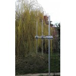
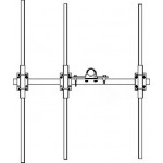
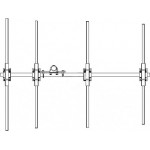
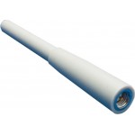
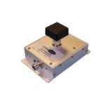
Antennes CASSEGRAIN 26,5 à 140 GHz
ELVA-1 ref.: ECA-XX, CASSEGRAIN
Nouveau
La très large gamme d'antennes CASSEGRAIN d'ELVA-1 permets de couvrir les bandes Ka, Q,U, V, E, W, F.
soit de 26,5 à 170 GHz , par bande
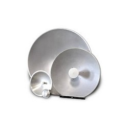
ELVA-1 has developed low-cost high-performance millimeter wave Cassegrain antennas to meet the needs of the broadband market. These antennas are dual reflector Cassegrain type ECA – XX series. Antennas of ECA – XX series are available for frequencies from 26.5 to 140 GHz with reflector diameters ranging from 100 to 900 mm.
The gain is up to 53 dBi depending on the frequency. The main reflector has a highly accurate surface and is made of aluminium. The sub-reflector is a machined aluminium hyperboloid or ellipsoid rigidly supported by a special plastic cylinder. These antennas are designed to have minimal cross-section to reduce aperture blockage, and hence produce low sidelobe levels (typically 18 dB). The typical VSWR is 1.25:1. The antenna’s gain depends upon its diameter.
The antenna feed is a circular waveguide of appropriate diameter with an optional circular-to-rectangular transition. D-band antennas for 110-170 GHz are also available by special orders.
Cassegrain Antennas Specifications
for Cassegrain antenna ECA – XX series
Ka-band, 26.5-40 GHz
| Part No | Diameter of main reflector (mm) | Gain dB (typ) |
Beam width at 3dB level deg. (typ) | VSWR (typ) |
| ECA-Ka-X-100 | 100 | 26.3 | 6.0 | 1.40 |
| ECA-Ka-X-200 | 200 | 32.7 | 2.9 | 1.35 |
| ECA-Ka-X-300 | 300 | 36.4 | 2.0 | 1.25 |
| ECA-Ka-X-450 | 450 | 40.9 | 1.3 | 1.25 |
| ECA-Ka-X-600 | 600 | 42.9 | 0.9 | 1/25 |
Losses in a Protected cover is 0.7 dB (max)
The feed waveguide is circular or rectangular
Information for Ordering: X= Number for the type of feed waveguide
Available types of Circular waveguides are:
| Number | Frequency Band (GHz) | Diameter of Waveguide (inch) | Flange |
| X=0 | 26.0-28.5 | 0.328 | UG-381/U |
| X=1 | 28.5-33.0 | 0.281 | UG-381/U |
| X=2 | 33.0-38.5 | 0.250 | UG-381/U |
| X=3 | 38.5-43.0 | 0.219 | UG-381/U |
Available type of Rectangular waveguide is:
| X=28 | 26.5-40 | WR-28 | UG-599/U UG-381/U UG-600 |
Data for Gain and Bandwidth are typical for the middle of the frequency range.
Q-band, 33-50 GHz
| Part No | Diameter of the main reflector (mm) | Gain, dB (typ) | Beam width at 3 dB level deg (typ) | VSWR (typ) |
| ECA-Q-X-100 | 100 | 28.3 | 4.8 | 1.40 |
| ECA-Q-X-200 | 200 | 34.6 | 2.3 | 1.35 |
| ECA-Q-X-300 | 300 | 38.5 | 1.6 | 1.25 |
| ECA-Q-X-450 | 450 | 42.9 | 1.0 | 1.25 |
| ECA-Q-X-600 | 600 | 44.9 | 0.7 | 1.25 |
| ECA-Q-X-900 | 900 | 47.0 | 0.4 | 1.25 |
Losses in a Protected cover is 0.7 dB (max)
The feed waveguide is circular or rectangular
Information for Ordering: X= Number for the type of feed waveguide
Available types of Circular waveguides are:
| Number | Frequency Band (GHz) | Diameter of Waveguide (inch) | Flange |
| X=0 | 33.0-38.5 | 0.250 | UG-383/U |
| X=1 | 38.5-43.0 | 0.219 | UG-383/U |
| X=2 | 43.0-50.0 | 0.188 | UG-383/U |
Available type of Rectangular waveguide is:
| X=22 | 33-50 | WR-22 | UG-383/U TRG719 |
Data for Gain and Bandwidth are typical for the middle of the frequency range.
U-band, 40-60 GHz
| Part No | Diameter of main reflector (mm) | Gain, dB (typ) |
Beam width at 3dB level deg (typ) | VSWR (typ) |
| ECA-U-X-100 | 100 | 32.0 | 3.9 | 1.35 |
| ECA-U-X-200 | 200 | 38.2 | 2.0 | 1.30 |
| ECA-U-X-300 | 300 | 41.7 | 1.3 | 1.25 |
| ECA-U-X-450 | 450 | 44.8 | 0.9 | 1.25 |
| ECA-U-X-600 | 600 | 46.4 | 0.7 | 1.25 |
Losses in a Protected cover is 0.7 dB (max)
The feed waveguide is circular or rectangular
Information for Ordering: X= Number for the type of feed waveguide
Available types of Circular waveguides are:
| Number | Frequency Band (GHz) | Diameter of Waveguide (inch) | Flange |
| X=0 | 38.5-43.0 | 0.219 | UG-383/U |
| X=1 | 43.0-50.0 | 0.188 | UG-383/U |
| X=2 | 50.0-58.0 | 0.165 | UG-383/U |
Available type of Rectangular waveguide is:
| X=19 | 40-60 | WR-19 | UG-383/U TRG720 |
Data for Gain and Bandwidth are typical for the middle of the frequency range.
V-band, 50-75 GHz
| Part No | Diameter of the main reflector (mm) | Gain, dB (typ) |
Beam width at 3dB level deg (typ) | VSWR (typ) |
| ECA-V-X-100 | 100 | 34.0 | 3.1 | 1.3 |
| ECA-V-X-200 | 200 | 39.7 | 1.5 | 1.25 |
| ECA-V-X-300 | 300 | 42.4 | 1.0 | 1.25 |
| ECA-V-X-450 | 450 | 45.4 | 0.7 | 1.25 |
| ECA-V-X-600 | 600 | 47.5 | 0.5 | 1.25 |
Losses in a Protected cover is 0.7 dB (max)
The feed waveguide is circular or rectangular
Information for Ordering: X= Number for the type of feed waveguide
Available types of Circular waveguides are:
| Number | Frequency Band (GHz) | Diameter of Waveguide (inch) | Flange |
| X=0 | 50.0-58.0 | 0.165 | UG-385/U |
| X=1 | 58.0-68.0 | 0.141 | UG-385/U |
| X=2 | 68.0-77.0 | 0.125 | UG-385/U |
Available type of Rectangular waveguide is:
| X=15 | 50-75 | WR-15 | UG-385/U |
Data for Gain and Bandwidth are typical for the middle of the frequency range.
E-band, 60-90 GHz
| Part No | Diameter of the main reflector (mm) | Gain, dB (typ) |
Beam width at 3dB level deg (typ) | VSWR (typ) |
| ECA-E-X-100 | 100 | 34.4 | 2.6 | 1.30 |
| ECA-E-X-200 | 200 | 39.9 | 1.3 | 1.25 |
| ECA-E-X-300 | 300 | 43.5 | 0.9 | 1.25 |
| ECA-E-X-450 | 450 | 46.6 | 0.6 | 1.25 |
| ECA-E-X-600 | 600 | 49.5 | 0.4 | 1.25 |
Losses in a Protected cover is 0.7 dB (max)
The feed waveguide is circular or rectangular
Information for Ordering: X= Number for the type of feed waveguide
Available types of Circular waveguides are:
| Number | Frequency Band (GHz) | Diameter of Waveguide (inch) | Flange |
| X=1 | 68.0-77.0 | 0.125 | UG-387/U |
| X=2 | 77.0-87.0 | 0.110 | UG-387/U |
| X=3 | 87.0-100.0 | 0.094 | UG-387/U |
Available type of Rectangular waveguide is:
| X=12 | 60-90 | WR-12 | UG-387/U |
Data for Gain and Bandwidth are typical for the middle of the frequency range.
W-band, 75-110 GHz
| Part No | Diameter of main reflector (mm) | Gain, dB (typ) | Beam width at 3dB level deg (typ) | VSWR (typ) |
| ECA-W-X-100 | 100 | 35.7 | 2.1 | 1.25 |
| ECA-W-X-200 | 200 | 41.7 | 1.0 | 1.25 |
| ECA-W-X-300 | 300 | 45.0 | 0.7 | 1.25 |
| ECA-W-X-450 | 450 | 48.0 | 0.5 | 1.25 |
| ECA-W-X-600 | 600 | 50.0 | 0.4 | 1.25 |
Losses in a Protected cover is 0.7 dB (max)
The feed waveguide is circular or rectangular
Information for Ordering: X= Number for the type of feed waveguide
Available types of Circular waveguides are:
| Number | Frequency Band (GHz) | Diameter of Waveguide (inch) | Flange |
| X=0 | 77.0-87.0 | 0.110 | UG-387/U-M |
| X=1 | 87.0-100.0 | 0.094 | UG-387/U-M |
| X=2 | 100.0-112.0 | 0.082 | UG-387/U-M |
Available type of Rectangular waveguide is:
| X=10 | 75-110 | WR-10 | UG-387/U-M |
Data for Gain and Bandwidth are typical for the middle of the frequency range.
F-band, 90-140 GHz
| Part No | Diameter of main reflector (mm) | Gain dB (typ) |
Beam width at 3dB level deg (typ) | VSWR (typ) |
| ECA-F-X-100 | 100 | 37.0 | 1.7 | 1.25 |
| ECA-F-X-200 | 200 | 42.6 | 0.9 | 1.25 |
| ECA-F-X-300 | 300 | 45.9 | 0.6 | 1.25 |
| ECA-F-X-450 | 450 | 48.0 | 0.5 | 1.25 |
Losses in a Protected cover is 0,7 dB (max)
The feed waveguide is circular or rectangular
Information for Ordering: X= Number for the type of feed waveguide
Available types of Circular waveguides are:
| Number | Frequency Band (GHz) | Diameter of Waveguide (inch) | Flange |
| X=0 | 87.0-100.0 | 0.094 | UG-387/U-M |
| X=1 | 100.0-112.0 | 0.082 | UG-387/U-M |
| X=2 | 112.0-125.0 | 0.075 | UG-387/U-M |
| X=3 | 125.0-140.0 | 0.067 | UG-387/U-M |
Available type of Rectangular waveguide is:
| X=8 | 90-140 | WR-8 | UG-387/U-M |
Data for Gain and Bandwidth are typical for the middle of the frequency range.
D-band, 110-170 GHz
| Part No | Diameter of main reflector (mm) | Gain dB (typ) |
Beam width at 3dB level deg (typ) | VSWR (typ) |
| ECA-D-X-100 | 100 | 40.3 | 1.4 | 1.25 |
| ECA-D-X-150 | 150 | 43.5 | 0.9 | 1.25 |
| ECA-D-X-200 | 200 | 46.1 | 0.7 | 1.25 |
| ECA-D-X-300 | 300 | 49.4 | 0.5 | 1.25 |
| ECA-D-X-450 | 450 | 52.0 | 0.3 | 1.25 |
Losses in a Protected cover is 1,0 dB (max)
The feed waveguide is circular or rectangular
Information for Ordering: X= Number for the type of feed waveguide
Available types of Circular waveguides are:
| Number | Frequency Band (GHz) | Diameter of Waveguide (inch) | Flange |
| X=0 | 110.0-140.0 | 0.073 | UG-387/U-M |
| X=1 | 140.0-160.0 | 0.059 | UG-387/U-M |
Available type of Rectangular waveguide is:
| X=8 | 110-170 | WR-6 | UG-387/U-M |
- Antenne CASSEGRAIN_1
ELVA-1 Antennes Cassegrain - Antenne CASSEGRAIN_2
ELVA-1 Antennes Cassegrain - Antenne CASSEGRAIN_3
ELVA-1 Antennes Cassegrain - Antenne CASSEGRAIN_4
ELVA-1 Antennes Cassegrain
No customer comments for the moment.
30 Nous vous proposons également
-
3030 Milliwattmetre...
-
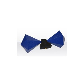
Antenne 138MHz à 6 GHz
-
AARONIA, Sondes PBS 2,...
-
RF One 3029...
-

TC-350 DMM/TDR...
-
ANTENNE Yagi 68/88 MHz...
-
ANTENNE Yagi 68/88 MHz...
-
ANTENNE Yagi 68/88 MHz...
-
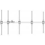
ANTENNE Yagi 68/88 MHz...
-

ITA6POM
-
BANC RADIO FREEDOM R8100
-
RFE GLOBAL FREEDOM R8000
-
Antenne AARONIA ref....
-
Antenne SMARTEQ
-
Charge 1 KW MICROSET
-
Charge 300 Watts MICROSET
-
Charge 30 Watts MICROSET
-
Répéteur GPS / GSNSS
-
Banc Radio...
-

3030 EXT...
-
SWR analyseur...
-
Analyseur de spectre...
-
Antenne AARONIA...
-
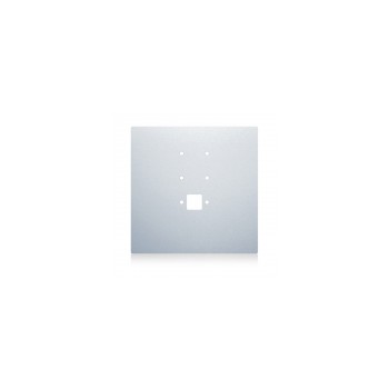
Plan de masse pour...
-
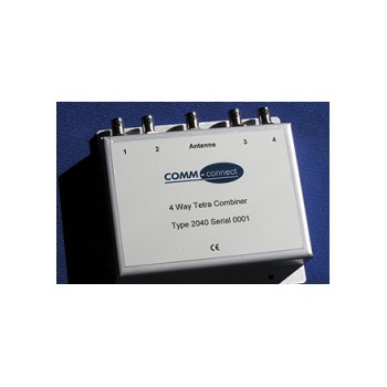
2040 COMBINER 360 /...
-
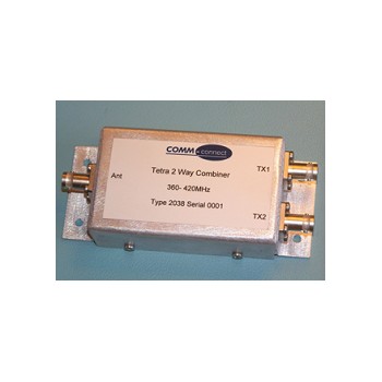
2038 COMBINER 360 /...
-
2043 COMBINER 360 /...
-
2044 COMBINER 360 /...
-
Bloc Alimentation de...
-
MobiBridge-10G radio...


